What is Injection Molding?
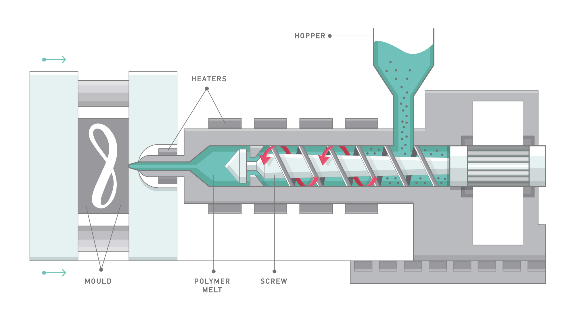
An injection molding press consists of two halves, a clamping side and an injection side. The main purpose of the clamping side is to open and close the mold and the ejection of the molded parts. The purpose of the injection unit is to melt the material by controlled heating and then to inject molten material into a mold.
The screw rotates with the rpm specified on the screen to melt material introduced from the hopper and to accumulate molten material in front of the screw. Aſter the required amount of molten material is accumulated by the screw retraction, the injection phase begins.
As molten material is introducing into the mold, the injection machine controls the ram speed of the screw or injection speed (speed profile). In addition to this, it controls the molding pressure aſter molten material fills into the cavities.
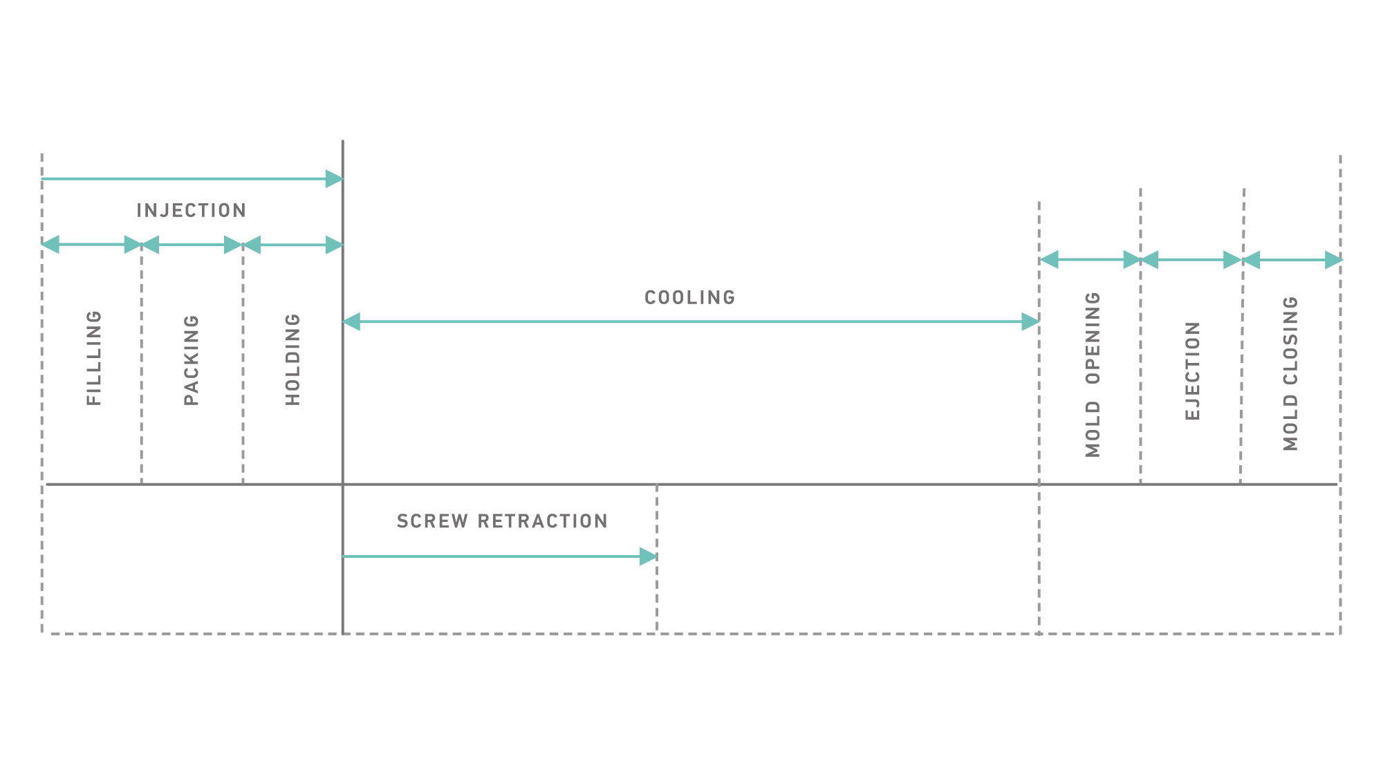
Injection Molding Cycle
Filling Phase
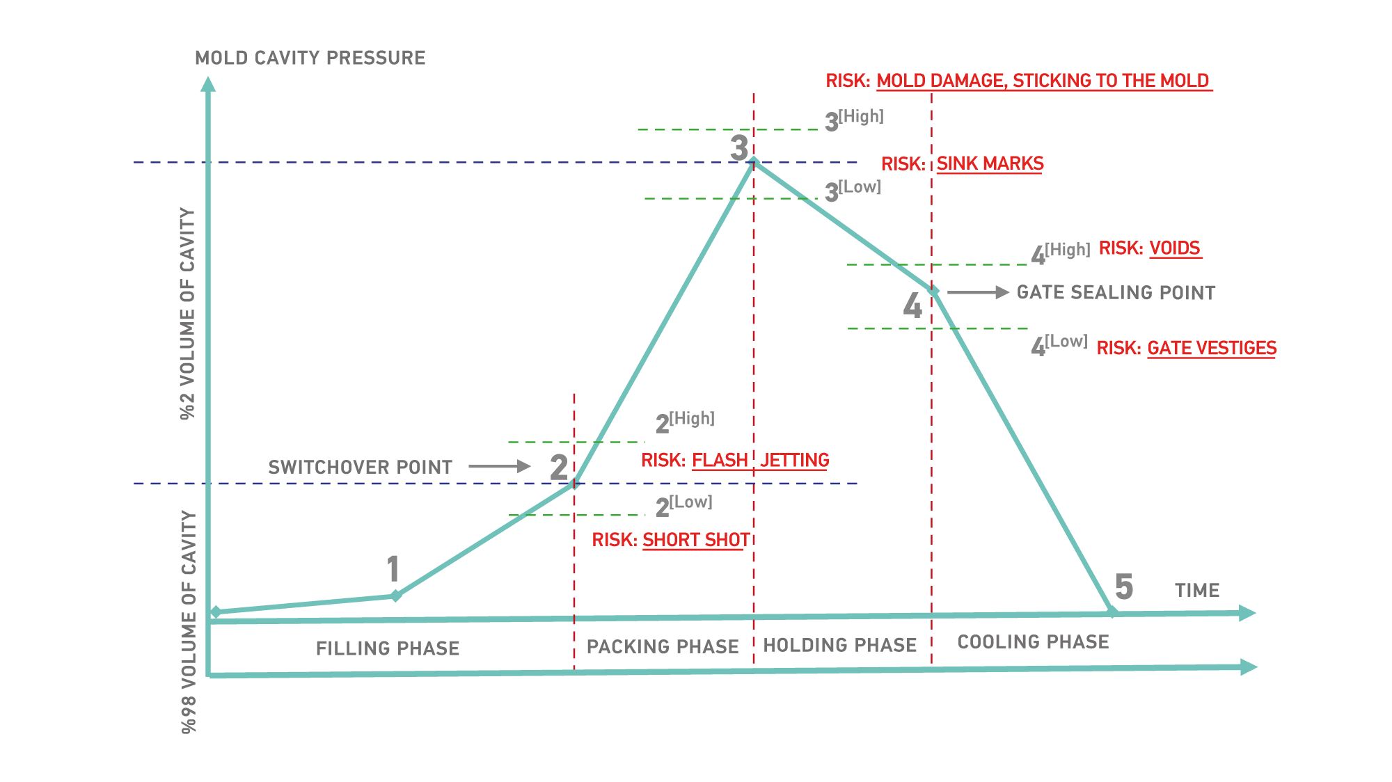
The melt must be filled to the mold as fast as possible according to the part geometry. If there are any restricted areas affecting the filling properties, the proper speed profile must be determined. The flow characteristics are determined by the melt temperature, the speed, and the shear rate. An injection speed that is too high can create excessive shear and result in defects, such as splay and jetting. High speed filling terminates at the Switchover point, and the low speed packing phase commences.
Switchover Point
It is a transition point from filling to packing, and plays a crucial role in the quality of the molded parts. Late switchover can cause building up of excessive cavity pressure, and it leads to flash and mold opening. Early switchover leads to short shots and longer cycle times.
Packing Phase
As soon as the material gets into the cavity, cooling starts and it induces shrinkage. That is why there is a need to inject more material in order to prevent this shrinkage. Aſter loading to 98% of the volume of cavity, the injection speed and pressure reduces during this phase. The packing pressure determines the part weight and part dimensions. It is important to completely fill the mold and avoid over packing 3[High] or under packing 3[Low].
Holding Phase
By reducing the pressure and applying speed, a certain amount of pressure must be applied until the gate completely freezes. Gate freezing is the solidification of material around the gate area and prevents the melt from back flowing out of the mold. This keeps the dimensions and weight values stable.
Gate Sealing Point
The plastic enters the cavity through the gate. As long as the gate is not frozen, new material comes in to the mold replacing unoccupied free spaces leſt from shrinking material. At the end of the solidification, the gate is completely blocked due to cooling and no material can get back to the flow path.
Cooling Phase
To ensure optimum molding cycles while maintaining part surface requirements and mold filling capability, a stable mold temperature should be determined and maintained. The cooling time takes about 80% of the injection molding cycle. A well-designed cooling system can shorten the molding time and improve productivity.
Injection Molding Recommendations
| INJECTION MOLDING RECOMMENDATIONS | |||||||||
|---|---|---|---|---|---|---|---|---|---|
| RECOMMENDATION | Elastron D | Elastron G | Elastron V | Elastron TPO | FR 6 Series | Bondable | |||
| G201 | Others | V101 | V201 | V601 | G601 | G500 | |||
| Drying temperatures | No need | 90 ℃ | 90 ℃ 2 hours recommended | 90 ℃ | 90 ℃ | No need | 90 ℃ | 90 ℃ | 80 ℃ |
| Drying time | 2 hours | 2 hours | 2 hours | 2 hours | 2 hours | 3 hours | |||
| Rear Zone temp. ℃ | 140 - 150 | 160 - 190 | 145 - 175 | 155 - 175 | 155 - 175 | 155 - 175 | 155 - 175 | 145 - 175 | 180 - 200 |
| Middle Zone temp. ℃ | 145 - 160 | 170 - 200 | 155 - 185 | 165 - 185 | 165 - 185 | 165 - 185 | 165 - 185 | 155 - 185 | 190 - 210 |
| Front Zone temp. ℃ | 150 - 165 | 175 - 205 | 160 - 190 | 170 - 190 | 170 - 190 | 175 - 195 | 170 - 190 | 160 - 190 | 205 - 220 |
| Nozzle Temperature ℃ | 165 - 185 | 190 - 220 | 175 - 205 | 180 - 210 | 180 - 210 | 195 - 225 | 180 - 210 | 175 - 205 | 220 - 230 |
| Injection Speed | Low | Mod / High | Low / Mod | Moderate | High | Mod / High | Moderate | Low / Mod | Mod / High |
| Injection Time sn | 3 - 5 | 1 - 3 | 3 - 5 | 2 - 4 | 1 - 3 | 1 - 3 | 2 - 4 | 2 - 4 | 1 - 4 |
| Injection Pressure bar | 10 - 40 | 10 - 40 | 10 - 40 | 10 - 40 | 10 - 40 | 10 - 40 | 10 - 40 | 10 - 40 | 10 - 40 |
| Hold Pressure bar | 5 - 20 | 5 - 20 | 5 - 20 | 5 - 20 | 5 - 20 | 5 - 20 | 5 - 20 | 5 - 20 | 5 - 20 |
| Back Pressure bar | 5 - 40 | 5 - 40 | 5 - 40 | 5 - 40 | 5 - 40 | 5 - 40 | 5 - 40 | 5 - 40 | 5 - 40 |
| Screw Speed (rpm) | 50 - 200 | 50 - 200 | 50 - 200 | 50 - 200 | 50 - 200 | 50 - 200 | 50 - 200 | 50 - 200 | 50 - 200 |
| Mold Temperature ℃ | 25 - 50 | 25 - 50 | 25 - 50 | 25 - 50 | 25 - 50 | 25 - 50 | 25 - 50 | 25 - 50 | 25 - 50 |
| Screw Comp. ratio | 1.5:1 – 2.0:1 | 1.5:1 – 3.0:1 | 1.5:1 – 2.0:1 | 1.5:1 – 2.0:1 | 2.0:1 – 4.0:1 | 2.0:1 – 4.0:1 | 1.5:1 – 3.0:1 | 1.5:1 – 3.0:1 | 2.0:1 – 4.0:1 |
| Screw L/D | 18 - 24 | 18 - 24 | 18 - 24 | 18 - 24 | 18 - 24 | 18 - 24 | 18 - 24 | 18 - 24 | 18 - 24 |
| Residence time | 1 - 2 shot | 1 - 2 shot | 1 - 2 shot | 1 - 2 shot | 1 - 2 shot | 1 - 2 shot | 1 - 2 shot | 1 - 2 shot | 1 - 2 shot |